
Introduction
- In computer networking, Cisco ASA 5500 Series Adaptive Security Appliances, or simply Cisco ASA, is Cisco’s line of network security devices introduced in May 2005, that succeeded three existing lines of popular Cisco products:
- Cisco PIX, which provided firewall and network address translation (NAT) functions ended sale on 28 July 2008.
- Cisco IPS 4200 Series, which worked as intrusion prevention systems (IPS).
- Cisco VPN 3000 Series Concentrators, which provided virtual private networking (VPN).
- The Cisco ASA is a unified threat management device, combining several network security functions in one box.
Cisco ASA Features
- antivirus
- antispam
- IDS/IPS engine
- VPN Device
- SSL Device
- content inspection
ASA Models and their throughputs
- Cisco ASA 5505
- Cisco ASA 5510
- Cisco ASA 5520
- Cisco ASA 5525-X
- Cisco ASA 5540
- Cisco ASA 5550
- Cisco ASA 5580-20
- Cisco ASA 5580-40
| Model | 5506-X | 5506W-X | 5506H-X | 5508-X | 5512-X | 5515-X | 5516-X | 5525-X | 5545-X | 5555-X | 5585-X |
| Throughput Gb/s | 0.25 | 0.25 | 0.25 | 0.45 | 0.3 | 0.5 | 0.85 | 1.1 | 1.5 | 1.75 | 4-40 |
| GB ports | 8 | 8 | 4 | 8 | 6 | 6 | 8 | 8 | 8 | 8 | 6-8 |
| Ten GB ports | 0 | 0 | 0 | 0 | 0 | 0 | 0 | 0 | 0 | 0 | 2-4 |
| Form factor | desktop | desktop | desktop | 1 RU | 1 RU | 1 RU | 1 RU | 1RU | 1RU | 1RU | 2RU |
ASA Architecture
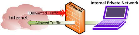
- ASA is an application-aware stateful packet filtering firewall
- Inspects all the packets which are passing through the firewall
- Each and every interface on ASA requires configuration of following parameters
ASA Architecture
- ASA is an application-aware stateful packet filtering firewall
- Inspects all the packets which are passing through the firewall
- Each and every interface on ASA requires configuration of following parameters
1.Interfaces with name and IP Address Add block
2.Security Level
ASA security levels
- By default ,the security level is automatically set to the interface once name is configured §ASA uses security level 100 for trusted or internal networks and 0 for un-trusted or public networks
- We can configure security levels to other interfaces also like DMZ 50
- By default, traffic from higher traffic level to lower are allowed or inspected, all other traffic is blocked


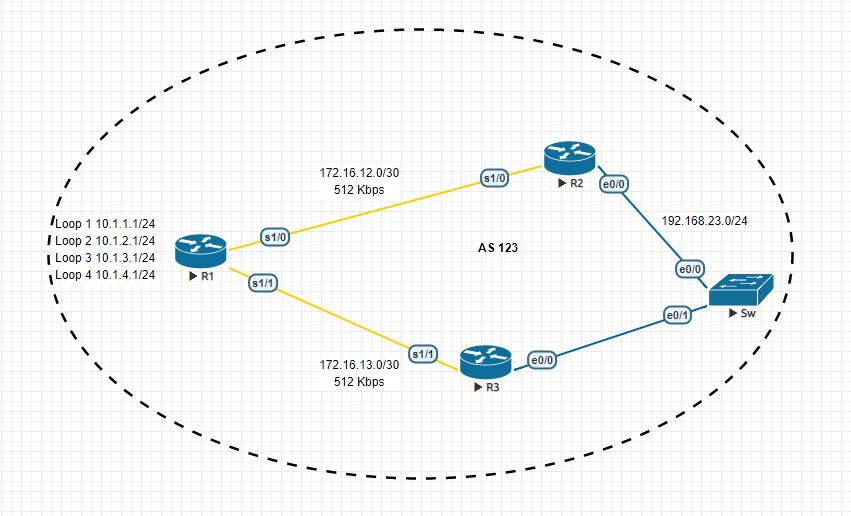

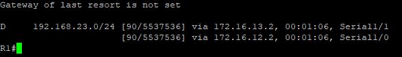
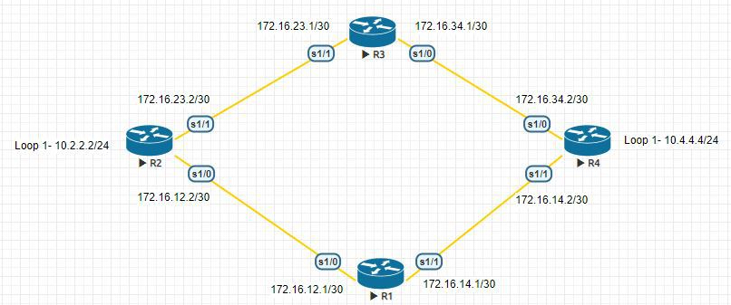
 Routing is the process of selecting paths for networks. We can use either Static or Dynamic method for this, in static routing the administrator itself assigning paths for each unknown networks but in the case of dynamic protocols are building paths for those unknown networks. There are some advantages and disadvantages for those two methods, like in static routing administrator overhead is very high but CPU overhead is less and in the case of dynamic routing administrator overhead is less but CPU overhead is very high. For small infrastructure static routing is enough, and we are using static routes with dynamic protocols that i will explain later.