Category: Networking

  • ✅Minimum Requirements of a Network

    1. At least Two Devices
      • Computers, servers, laptops, printers, or even smartphones.
      • Example: Two PCs connected together form the smallest network.
    2. Network Interface Card (NIC)
      • Each device needs a network adapter (wired Ethernet port or Wi-Fi card) to connect to the network.
    3. Transmission Medium (Communication Channel)
      • Can be wired (Ethernet cables, fiber optic) or wireless (Wi-Fi, Bluetooth, infrared).
    4. Networking Device (Optional but Common)
      • Switch/Hub – to connect multiple devices in LAN.
      • Router – to connect LAN to the Internet or other networks.
    5. Network Protocols
      • Common “language” computers use to communicate.
      • Most common: TCP/IP (Transmission Control Protocol/Internet Protocol).
    6. IP Addressing
      • Every device must have a unique IP address to identify itself on the network.
    7. Operating System / Network Software
      • To manage network communication.
      • Example: Windows, Linux, macOS, or specialized network OS.

    👉 In short:
    A minimum network = 2 devices + NICs + connection medium + protocol (TCP/IP).
    For bigger networks, you add switches, routers, servers, firewalls, etc.

  • ✅What is a Computer Network?

    A computer network is a collection of two or more computers (or devices like printers, servers, switches, routers) that are connected together to share resources (files, applications, printers), communicate, or access the internet.

    Example: Your home Wi-Fi is a small computer network.


    ✅ Types of Networks

    Networks are classified mainly by size/area covered:

    1. LAN (Local Area Network)
      • Covers small area (office, home, school).
      • High speed, low cost.
      • Example: Office network with 10 PCs and a printer.
    2. WAN (Wide Area Network)
      • Covers large geographical area (countries, worldwide).
      • Internet is the largest WAN.
      • Example: Bank ATMs connected nationwide.
    3. MAN (Metropolitan Area Network)
      • Covers a city or large campus.
      • Example: Cable TV network, city-wide Wi-Fi.
    4. PAN (Personal Area Network)
      • Very small range, usually within a few meters.
      • Example: Bluetooth between phone and headphones.

    👉 Other categories: CAN (Campus Area Network), SAN (Storage Area Network), VPN (Virtual Private Network).


    ✅ Uses of Networks

    • Resource Sharing – printers, files, applications.
    • Communication – email, chat, video calls.
    • Centralized Data Management – store & secure data in servers.
    • Scalability – add users without much cost.
    • Internet Access Sharing – one internet line for many users.

    ✅ Domain vs Workgroup

    🔹 Workgroup

    • Peer-to-peer network (no central control).
    • Each computer manages its own settings and logins.
    • Good for small networks (≤10 PCs) like home or small office.
    • Example: You can share files between two laptops at home using a workgroup.

    🔹 Domain

    • Client–Server model (centralized control).
    • Managed by a server (Domain Controller – DC).
    • Centralized authentication (same username/password works on all PCs).
    • Good for large organizations (hundreds of computers).
    • Example: In an office, you log into your PC using your company credentials (Windows Active Directory domain).

    👉 In short:

    • Workgroup = Simple, decentralized, for small networks.
    • Domain = Centralized, secure, scalable, for enterprise.
  • High Availability (HA) configuration for Cisco Meraki MX67

    ⚙️ About HA in Meraki MX67

    • Meraki MX67 supports Warm Spare / High Availability (HA) in Active–Passive mode.
    • You need two MX67 appliances (same model) and Advanced Security license for each (or a single shared license if you have Meraki’s per-network licensing).
    • The HA works by monitoring uplinks and LAN, and failing over automatically if the primary fails.

    🛠 How to configure HA in Meraki MX67

    ✅ 1. Physical setup

    • Place both MX67 units on the same LAN segment.
    • Connect:
      • Each MX to the Internet (same or different uplinks).
      • The LAN ports of both MXs to the same switch or switches.
    • Connect the dedicated HA/Spare port (Port 4 on MX67) from the primary to the secondary (this is the Heartbeat connection).

    Tip: Make sure the heartbeat cable is direct or via switch but must be in the same VLAN/subnet.


    ✅ 2. Configure in Meraki Dashboard

    1. Go to: Security & SD-WAN > Monitor > Appliance status
    2. Add the secondary MX:
      • Go to Security & SD-WAN > Configure > Addressing & VLANs.
      • Enable Warm Spare.
    3. Enter the serial number of the secondary MX in the Warm Spare field.
    4. Dashboard automatically creates:
      • Shared Virtual IP (VIP) for WAN.
      • Shared Virtual IP for LAN.

    ⚠ Both MXs must be in the same network in the Meraki Dashboard.


    ✅ 3. WAN configuration

    • If you have multiple WAN uplinks, configure WAN1 and WAN2 on both MXs identically.
    • Ensure the ISP allows the use of a Virtual IP (VIP).

    ✅ 4. LAN configuration

    • LAN interfaces should be identical.
    • Enable Use MX uplink IPs or configure Virtual IPs:
      • WAN VIP: shared IP that moves between MXs.
      • MX uplink IPs: individual IPs on each MX.

    📊 Failover

    • Heartbeat checks happen over the dedicated HA port.
    • Failover typically occurs in seconds (about 30 seconds or less).

    Verify HA status

    • In Dashboard: Security & SD-WAN > Appliance status → Warm Spare status shows which is active.
    • You can simulate failover by disconnecting the primary MX uplink.

    🔒 Important notes:

    • Meraki MX HA is Active-Passive; no Active-Active.
    • Both MXs must be the same model and firmware.
    • Heartbeat connection is essential for proper failover detection.
    • Use Virtual IP for seamless failover.
  • How to set a bandwidth restriction per individual user on Sophos Firewall (SFOS v19.5 or v20.x)

    Goal:

    Limit each user to:

    • Download: 2 Mbps
    • Upload: 512 Kbps

    (You can change numbers as needed.)


    🛠 Step-by-step

    Step 1: Create Traffic Shaping Policy

    1. Log in to Sophos Firewall web admin (https://<firewall-ip>:4444)
    2. Go to:
      Protect > Traffic Shaping
    3. Click Add
    4. Fill like this:
      | Field | Example |
      |——|———|
      | Name | Limit_2Mbps_per_user |
      | Policy Association | User |
      | Rule type | Individual |
      | Priority | 5 (lower is higher priority) |
      | Bandwidth usage type | Limit |
      | Guaranteed bandwidth | (leave empty) |
      | Maximum bandwidth (download) | 2048 Kbps |
      | Maximum bandwidth (upload) | 512 Kbps |

    Save


    Step 2: Apply to individual users

    1. Go to:
      Authentication > Users
    2. Click on the user you want to limit
    3. Under Traffic shaping policy, choose:
      Limit_2Mbps_per_user
    4. Save

    Repeat for each user you want to limit.


    Step 3: Confirm the firewall rule matches

    Bandwidth limit only applies to traffic that matches a firewall rule.

    1. Go to:
      Rules and Policies > Firewall Rules
    2. Confirm you have a rule like:
    • Source zone: LAN
    • Destination zone: WAN
    • User/Network: Any or specific users
    1. If you already have a firewall rule for internet access, you don’t need to change it.
    2. If you want to create a dedicated rule:
    • Click Add Firewall Rule > New User/Network Rule
    • Source zone: LAN
    • Destination zone: WAN
    • Source network: users you want to limit
    • Apply as needed

    Step 4: Test & Monitor

    Go to:
    Monitor & Analyze > Current Activities > Live Users

    Watch the bandwidth column to see usage stays around your limit.

    You can also see under:

    • Monitor & Analyze > Current Activities > Live Connections

    📝 Sample Traffic Shaping Policy Screenshot (for reference)

    NameLimit_2Mbps_per_user
    Policy associationUser
    Rule typeIndividual
    Priority5
    Guaranteed download(leave empty)
    Guaranteed upload(leave empty)
    Max download2048 Kbps
    Max upload512 Kbps

    Summary

    • Create a User-based, Individual traffic shaping policy
    • Apply it to each user under Authentication > Users
    • Make sure there’s a firewall rule that matches those users’ traffic
  • SNMP v2c on Aruba (HPE) switch

    Here’s how to configure SNMP v2c on an Aruba (HPE) switch, specifically for the ArubaOS-Switch series (formerly HP ProCurve).


    🔧 SNMP v2c Configuration Steps – ArubaOS-Switch (CLI)

    1. Enable SNMP Service (if not already enabled)

    switch(config)# snmp-server

    2. Set the SNMP Read-Only Community String

    switch(config)# snmp-server community public operator-unrestricted

    • public – replace with your preferred community string.
    • operator-unrestricted – gives read-only access.

    3. Set the SNMP Read-Write Community String (if needed)

    switch(config)# snmp-server community private manager-unrestricted

    • private – change to a secure community name.
    • manager-unrestricted – allows full configuration access.

    4. Define SNMP Trap Receiver (Optional)

    switch(config)# snmp-server host 192.168.1.100 community public

    • Replace 192.168.1.100 with your SNMP monitoring server IP.

    5. Enable SNMP Traps (Optional)

    switch(config)# snmp-server enable traps


    ✅ Example Configuration

    switch(config)# snmp-server switch(config)# snmp-server community monitor operator-unrestricted switch(config)# snmp-server community manage manager-unrestricted switch(config)# snmp-server host 192.168.1.10 community monitor switch(config)# snmp-server enable traps


    🔍 To Verify Configuration

    show snmp-server


  • Dual internet configuration using BGP in cisco router

    To configure dual internet connections using BGP on a Cisco router for redundancy and failover, follow these key steps and considerations:

    Basic BGP Configuration

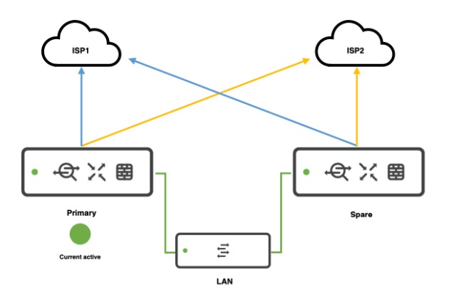
    Establish BGP Sessions with Both ISPs
    Configure BGP neighbors using the ISPs’ AS numbers and your assigned ASN. For example:
    router bgp 65001
    neighbor 203.0.113.1 remote-as ISP1_ASN
    neighbor 198.51.100.1 remote-as ISP2_ASN
    address-family ipv4
    network 192.0.2.0 mask 255.255.255.0 # Advertise your public subnet
    exit-address-family

    Replace ISP1_ASN and ISP2_ASN with the respective ISP AS numbers

    Advertise Networks
    Use the network command to announce your public IP ranges to both ISPs. Ensure both ISPs accept the advertised prefixes

    Traffic Control and Path Selection

    Outbound Traffic

    Local Preference: Prioritize one ISP for outbound traffic by setting a higher local preference (default is 100):

    route-map PREFER_ISP1 permit 10

    set local-preference 200

    !

    router bgp 65001

    neighbor 203.0.113.1 route-map PREFER_ISP1 in

    This makes ISP1 the preferred path

    Inbound Traffic

    AS Path Prepending: Lengthen the AS path for the backup ISP to make the primary ISP more attractive:

    route-map PREPEND_ISP2 out

    set as-path prepend 65001 65001 65001

    !

    router bgp 65001

    neighbor 198.51.100.1 route-map PREPEND_ISP2 out

    This reduces the likelihood of inbound traffic using ISP2 unless ISP1 fails

    Failover Mechanisms

    BGP Conditional Advertisement
    Advertise routes to the backup ISP only if the primary ISP’s BGP session fails:

    router bgp 65001

    neighbor 198.51.100.1 advertise-map ADVERTISE_ONLY_IF_ISP1_DOWN non-exist-map CHECK_ISP1

    !

    ip prefix-list ISP1_ROUTES seq 5 permit 203.0.113.0/24

    !

    route-map CHECK_ISP1 permit 10

    match ip address prefix-list ISP1_ROUTES

    !

    route-map ADVERTISE_ONLY_IF_ISP1_DOWN permit 10

    set ip address prefix-list YOUR_PUBLIC_SUBNET

    This ensures ISP2 receives your prefix only when ISP1 is unavailable

    Fast External Fall over
    Enable rapid detection of link failures:

    router bgp 65001

    bgp fast-external-fallover

    This terminates BGP sessions immediately if the physical interface goes down3.

    Additional Considerations

    • NAT Configuration: If using NAT, ensure the firewall or router translates internal addresses to the public IPs provided by the primary ISP. Verify the secondary ISP allows routing the primary’s IP range35.
    • Default Routes: Receive default routes from both ISPs using neighbor <IP> default-originate or configure static defaults with floating AD values for backup25.
    • Route Filtering: Use prefix-lists or route-maps to filter unwanted routes from ISPs to prevent becoming a transit AS5.

    Verification Commands

    • Check BGP neighbor status:
      show ip bgp summary
    • Verify advertised/received routes:
      show ip bgp neighbors <IP> advertised-routes
      show ip bgp neighbors <IP> routes
    • Monitor path selection:
      show ip bgp

    By combining these techniques, you achieve redundancy, control traffic flow, and automate failover. Always coordinate with ISPs to ensure they accept your BGP policies

  • Enhanced Python script for Meraki Switch with VLAN deletion or port monitoring

    • ✅ VLAN creation
    • ❌ VLAN deletion
    • 🔧 Switch port config
    • 👀 Port monitoring (get port status like usage, errors)

    🧰 Full Python Script – Meraki Switch Automation

    import requests

    # Config
    API_KEY = "YOUR_MERAKI_API_KEY"
    ORG_ID = "YOUR_ORG_ID"
    NETWORK_ID = "YOUR_TEMPLATE_BOUND_NETWORK_ID"
    DEVICE_SERIAL = "YOUR_SWITCH_SERIAL" # Example: Q2XX-XXXX-XXXX

    BASE_URL = "https://api.meraki.com/api/v1"

    HEADERS = {
    "X-Cisco-Meraki-API-Key": API_KEY,
    "Content-Type": "application/json"
    }

    # --- VLAN FUNCTIONS ---

    # ✅ Create VLAN
    def create_vlan(vlan_id, name, subnet, appliance_ip):
    url = f"{BASE_URL}/networks/{NETWORK_ID}/vlans"
    payload = {
    "id": vlan_id,
    "name": name,
    "subnet": subnet,
    "applianceIp": appliance_ip
    }
    response = requests.post(url, headers=HEADERS, json=payload)
    print(f"[CREATE VLAN {vlan_id}] Status: {response.status_code} - {response.text}")

    # ❌ Delete VLAN
    def delete_vlan(vlan_id):
    url = f"{BASE_URL}/networks/{NETWORK_ID}/vlans/{vlan_id}"
    response = requests.delete(url, headers=HEADERS)
    print(f"[DELETE VLAN {vlan_id}] Status: {response.status_code} - {response.text}")

    # --- PORT FUNCTIONS ---

    # 🔧 Configure Switch Port
    def configure_switch_port(port_number, port_name="Trunk Port", allowed_vlans="1,10,20"):
    url = f"{BASE_URL}/devices/{DEVICE_SERIAL}/switch/ports/{port_number}"
    payload = {
    "name": port_name,
    "type": "trunk",
    "vlan": 1,
    "allowedVlans": allowed_vlans,
    "poeEnabled": True,
    "rstpEnabled": True,
    "stpGuard": "disabled"
    }
    response = requests.put(url, headers=HEADERS, json=payload)
    print(f"[CONFIGURE PORT {port_number}] Status: {response.status_code} - {response.text}")

    # 👀 Get Port Status
    def get_port_status():
    url = f"{BASE_URL}/devices/{DEVICE_SERIAL}/switch/ports"
    response = requests.get(url, headers=HEADERS)
    if response.status_code == 200:
    ports = response.json()
    for port in ports:
    print(f"Port {port['portId']}: {port.get('enabled', 'N/A')} | "
    f"Type: {port.get('type')} | VLAN: {port.get('vlan')} | "
    f"Usage: {port.get('usageInKb', 'N/A')} Kbps")
    else:
    print(f"[GET PORT STATUS] Error: {response.status_code} - {response.text}")

    # --- EXECUTION ---

    # VLAN Management
    create_vlan(10, "Staff", "192.168.10.0/24", "192.168.10.1")
    create_vlan(20, "IoT", "192.168.20.0/24", "192.168.20.1")
    # delete_vlan(20) # Uncomment to delete VLAN 20

    # Port Configurations
    configure_switch_port(1)
    configure_switch_port(2, port_name="Uplink to Router")

    # Port Monitoring
    get_port_status()


    ✅ Output Example:

    [CREATE VLAN 10] Status: 201 - {"id":"10",...}
    [CONFIGURE PORT 1] Status: 200 - { ... }
    Port 1: True | Type: trunk | VLAN: 1 | Usage: 120 Kbps


    🛡️ Recommendations:

    • Use environment variables or config files for sensitive info (API keys).
    • Add retry logic or logging for production scripts.
    • Use the Meraki Python SDK (meraki package) if you prefer an abstracted interface.
  • Python script using the Meraki Dashboard API to automate switch port configuration and VLAN creation in a template-bound network.

    🔐 Step 1: Setup

    Make sure you have:

    • API key from Meraki Dashboard (keep it secret!)
    • Template-bound Network ID
    • requests library installed (pip install requests)

    🧠 Step 2: Python Script

    import requests

    # Replace with your Meraki API key
    API_KEY = "YOUR_MERAKI_API_KEY"
    ORG_ID = "YOUR_ORG_ID"
    NETWORK_ID = "YOUR_TEMPLATE_BOUND_NETWORK_ID"
    DEVICE_SERIAL = "YOUR_SWITCH_SERIAL" # e.g., Q2XX-XXXX-XXXX

    # Meraki base URL
    BASE_URL = "https://api.meraki.com/api/v1"

    # Headers
    HEADERS = {
    "X-Cisco-Meraki-API-Key": API_KEY,
    "Content-Type": "application/json"
    }

    # Step 1: Create VLAN
    def create_vlan(vlan_id, name, subnet, appliance_ip):
    url = f"{BASE_URL}/networks/{NETWORK_ID}/vlans"
    payload = {
    "id": vlan_id,
    "name": name,
    "subnet": subnet,
    "applianceIp": appliance_ip
    }
    response = requests.post(url, headers=HEADERS, json=payload)
    print(f"VLAN Creation ({vlan_id}):", response.status_code, response.text)

    # Step 2: Configure a switch port
    def configure_switch_port(port_number):
    url = f"{BASE_URL}/devices/{DEVICE_SERIAL}/switch/ports/{port_number}"
    payload = {
    "name": "Uplink Port",
    "type": "trunk",
    "vlan": 1,
    "allowedVlans": "1,10,20",
    "poeEnabled": True,
    "rstpEnabled": True,
    "stpGuard": "disabled"
    }
    response = requests.put(url, headers=HEADERS, json=payload)
    print(f"Port {port_number} Config:", response.status_code, response.text)

    # --- Execution ---
    # Create VLANs
    create_vlan(10, "Staff", "192.168.10.0/24", "192.168.10.1")
    create_vlan(20, "IoT", "192.168.20.0/24", "192.168.20.1")

    # Configure ports 1 and 2 as trunk ports
    configure_switch_port(1)
    configure_switch_port(2)


    📝 Customize As Needed

    • Change NETWORK_ID and DEVICE_SERIAL to match your environment.
    • You can loop through multiple ports/VLANs for bulk updates.
    • Add error handling for production use.
  • How to Create and Modify Meraki Switch Templates

    🧩 1. What is a Meraki Switch Template?

    In Cisco Meraki, templates are configurations that can be applied across multiple networks, especially useful in large-scale deployments to ensure consistency.

    • A switch template allows you to configure:
      • VLANs
      • Port settings
      • STP settings
      • QoS policies
      • Link aggregation
      • Access policies (802.1X)
      • Voice VLANs
      • PoE settings

    🖥️ 2. Creating a Switch Template (via GUI)

    • Login to the Meraki Dashboard
    • Go to:
      Organization > Configuration templates
    • Click “Create a new template”
    • Name your template (e.g., Branch-Switch-Template)
    • Click Create
    • Click on the template name → Switch tab
    • Configure:
      • VLANs under Switch settings > Routing and DHCP
      • Per-port settings via Switch ports
      • QoS, STP, etc. under Switch settings
    • Bind networks to this template under:
      Organization > Configuration templates > Template > Bind networks

    ⚙️ 3. Modifying a Switch Template (via GUI)

    • Go to:
      Organization > Configuration templates > [Your Template]
    • Under the Switch tab, modify:
      • VLANs
      • Switch port configs
      • Layer 3 interfaces
      • Access policies
    • Changes auto-apply to all bound networks

    🔧 4. Creating/Modifying Switch Templates (via API)

    📌 Prerequisites:

    • Dashboard API key
    • Network ID or template ID
    • API base URL: https://api.meraki.com/api/v1

    ✅ Create a Configuration Template:

    POST /organizations/{organizationId}/configTemplates

    {
    "name": "Branch Switch Template"
    }

    ✅ Modify VLAN Settings in a Template:

    PUT /networks/{networkId}/switch/settings

    {
    "vlan": 20,
    "useCombinedPower": true,
    "voiceVlanId": 100
    }

    ✅ Update Switch Port:

    PUT /devices/{serial}/switch/ports/{portId}

    {
    "name": "Uplink Port",
    "type": "trunk",
    "vlan": 1,
    "allowedVlans": "1,10,20",
    "poeEnabled": true
    }

    📚 Extra Notes:

    • Templates can be bound to multiple networks. Once bound, you cannot configure those networks individually, unless you unbind them.
    • Best Practice: Create staging/testing networks to validate templates before applying widely.
  • How to enable Meraki API

    The Meraki API allows you to automate and manage your Meraki network programmatically. It is a RESTful API that provides access to Meraki dashboard data and configurations.


    1. Enable Meraki API

    Before using the API, you must enable it in the Meraki Dashboard:

    • Login to Meraki Dashboarddashboard.meraki.com
    • Go to “Organization” > “Settings”
    • Scroll to “Dashboard API access” and toggle it ON.
    • Click “Save”.

    2. Generate an API Key

    • Go to “My Profile” (top-right corner in the dashboard).
    • Scroll to “API access”.
    • Click “Generate API Key”.
    • Copy and save the API Key (It won’t be shown again).

    ⚠️ Security Note: Treat your API key like a password—never expose it in public or store it in unsecured locations.


    3. Test API Connectivity

    Use Postman or cURL to test API access.

    Example: Get Organization List

    Using cURL:

    curl -L -H "X-Cisco-Meraki-API-Key: YOUR_API_KEY" \
    -H "Content-Type: application/json" \
    -X GET "https://api.meraki.com/api/v1/organizations"

    Using Python:

    import requests

    API_KEY = "YOUR_API_KEY"
    url = "https://api.meraki.com/api/v1/organizations"

    headers = {
    "X-Cisco-Meraki-API-Key": API_KEY,
    "Content-Type": "application/json"
    }

    response = requests.get(url, headers=headers)
    print(response.json())

    4. Common Meraki API Endpoints

    Here are some useful endpoints:

    Organization Management

    ActionMethodEndpoint
    List organizationsGET/organizations
    Get org detailsGET/organizations/{orgId}
    Claim devices to orgPOST/organizations/{orgId}/claim

    Network Management

    ActionMethodEndpoint
    List networksGET/organizations/{orgId}/networks
    Create a networkPOST/organizations/{orgId}/networks
    Delete a networkDELETE/networks/{networkId}

    Device Management

    ActionMethodEndpoint
    List devices in a networkGET/networks/{networkId}/devices
    Get device detailsGET/devices/{serial}
    Update device settingsPUT/devices/{serial}

    5. Advanced Usage

    • Meraki Python SDK: Use the official Meraki Python library for easier API calls. bashCopyEditpip install meraki pythonCopyEditimport meraki API_KEY = "YOUR_API_KEY" dashboard = meraki.DashboardAPI(API_KEY) orgs = dashboard.organizations.getOrganizations() print(orgs)
    • Webhooks: Configure webhooks for real-time alerts.
    • Automation: Automate network provisioning, VLAN assignments, SSID management, etc.

    6. API Documentation

    For a complete list of API endpoints, visit Meraki API Docs.