Author: renjithbs

  • Basic VoIP Configuration in Cisco Packet Tracer 7.2

    Here i am going to explain how to setup a small VoIP lab in latest packet tracer.
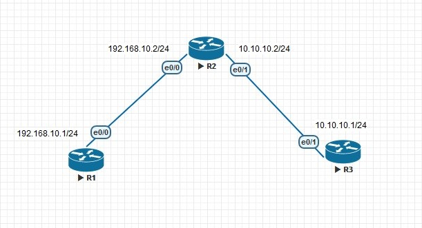
    Network Topology

    VOIP1.JPG

    Configurations

    1.DHCP & Interface configurations in C2811

    !
    hostname CME
    !
    ip dhcp pool DATA
    network 10.1.10.0 255.255.255.0
    default-router 10.1.10.254
    ip dhcp pool VOIP
    network 10.1.20.0 255.255.255.0
    default-router 10.1.20.254
    option 150 ip 10.1.20.254
    !
    interface FastEthernet0/0
    no ip address
    duplex auto
    speed auto
    !
    interface FastEthernet0/0.10
    encapsulation dot1Q 10
    ip address 10.1.10.254 255.255.255.0
    !
    interface FastEthernet0/0.20
    encapsulation dot1Q 20
    ip address 10.1.20.254 255.255.255.0
    !
    end

    2.CME Telephony configuration in C2811

    CME(config)#telephony-service             #telephony service
    CME(config-telephony)#max-ephones 5 #maximum number of phones
    CME(config-telephony)#max-dn 5        #maximum number of telephony numbers
    CME(config-telephony)#ip source-address 10.1.20.254 port 2000  #source IP address
    CME(config-telephony)#auto assign 4 to 6  #ext numbers to buttons
    CME(config-telephony)#auto assign 1 to 5  #ext numbers to buttons

    3.Phone directory for phones

    CME(config)#ephone-dn 1       #directory entry
    CME(config-ephone-dn)#number 54001                #phone number to this entry
    !
    CME(config)#ephone-dn 2         #directory entry
    CME(config-ephone-dn)#number 54002                #phone number to this entry

    4.Voice VLAN configuration 

    hostname S1
    !
    vlan 10
    name DATA
    vlan 20
    name VOIP

    !

    interface FastEthernet0/1
    switchport mode trunk
    !
    interface FastEthernet0/2
    switchport access vlan 10
    switchport mode access
    switchport voice vlan 20
    spanning-tree portfast
    !
    interface FastEthernet0/3
    switchport access vlan 10
    switchport mode access
    switchport voice vlan 20
    spanning-tree portfast
    !

    Verification

    Try to call from one phone to another 🙂 🙂 If you have any doubt please reach out to me


  • Simple Batch Script for Changing Proxy Options

    When we take our office laptop to home the main headache is changing the  proxy settings to access internet. Download the zip file unzip it into a folder there are two files, one for Turnoff Proxy another for Turn on Proxy.

    Download Link —-> Proxy


    Proxy1

    Enjoy 🙂 🙂

  • Simple Batch Script for Ping Sweep

    This is a tiny batch script to check live hosts in network . Download the zip file and unzip contents to a folder and put your device names in servers.txt file.  After that Run the script file it will do ping test and save the output in results.txt file.

    Download  link —->    Ping Script

    Ping1Ping2Ping3Ping4

    If you have any doubt please reach out to me 🙂 🙂


  • Traffic Engineering in EIGRP using Delay

    Here i am going to explain how to change paths using delay in EIGRP, We already know that EIGRP uses Bandwidth and Delay for metric calculation but we cant change bandwidth of links in production network . The path with lesser delay will be the desired path.

    EIGRP-Composite-Metric-Formula

    EIGRP_1


    In the above topology there are two paths to reach 192.168.23.0/24 network from R1  and right now R1 uses both links for load balancing because both having same metric.But i want to use only path to reach that destination and i going to do that with the help of delay.

    EIGRP_delayEIGRP_delay_1EIGRP_delay_2

    I am going to decrease  the delay in R1->R3 by that metric will also decrease and R1 prefer that path to reach 192.168.23.0/24.

    R1

    interface Serial1/1
    bandwidth 512
    ip address 172.16.13.1 255.255.255.252
    delay 1000
    serial restart-delay 0
    end

    EIGRP_delay_3EIGRP_delay_4

    Now there is only one path to reach that network 🙂

  • Update Tuning in RIPv2

    In RIPv2 we can tune its updates there are so many ways , Lets see some of them

    Default

    RIPv2 Broadcast updates

    Normally RIPv2 uses 224.0.0.9 as the multicast address but we can change it to global broadcast address.

    debug ip rip of R1 is given below

    *Sep 25 14:38:38.069: RIP: sending v2 update to 224.0.0.9 via Serial1/1 (172.16.14.1)
    *Sep 25 14:38:38.069: RIP: build update entries
    *Sep 25 14:38:38.069: 10.2.2.0/24 via 0.0.0.0, metric 2, tag 0
    *Sep 25 14:38:38.069: 172.16.12.0/30 via 0.0.0.0, metric 1, tag 0
    *Sep 25 14:38:38.069: 172.16.23.0/30 via 0.0.0.0, metric 2, tag 0

    I am going to change this
    interface Serial1/1
    ip rip v2-broadcast

    Now RIPv2 is using 255.255.255.255 for its updates
    *Sep 25 15:21:33.899: RIP: sending v2 update to 255.255.255.255 via Serial1/1 (172.16.14.1)
    *Sep 25 15:21:33.899: RIP: build update entries
    *Sep 25 15:21:33.899: 10.2.2.0/24 via 0.0.0.0, metric 2, tag 0
    *Sep 25 15:21:33.899: 172.16.12.0/30 via 0.0.0.0, metric 1, tag 0
    *Sep 25 15:21:33.899: 172.16.23.0/30 via 0.0.0.0, metric 2, tag 0

    RIPv2 Unicast Updates

    To change to uni cast updates follow these mentioned commands
    router rip
    version 2
    passive-interface Serial1/0
    passive-interface Serial1/1
    network 172.16.0.0
    neighbor 172.16.12.1
    neighbor 172.16.23.1
    no auto-summary

    Now RIP is sending updates to those neighbors only
    *Sep 25 15:26:54.423: RIP: sending v2 update to 172.16.12.1 via Serial1/0 (172.16.12.1)
    *Sep 25 15:26:54.423: RIP: build update entries
    *Sep 25 15:26:54.423: 10.4.4.0/24 via 0.0.0.0, metric 2, tag 0
    *Sep 25 15:26:54.423: 172.16.14.0/30 via 0.0.0.0, metric 1, tag 0
    *Sep 25 15:26:54.423: 172.16.34.0/30 via 0.0.0.0, metric 2, tag 0
    *Sep 25 15:26:54.423: RIP: sending v2 update to 172.16.23.1 via Serial1/0 (172.16.12.1)
    *Sep 25 15:26:54.423: RIP: build update entries
    *Sep 25 15:26:54.423: 10.4.4.0/24 via 0.0.0.0, metric 2, tag 0
    *Sep 25 15:26:54.423: 172.16.14.0/30 via 0.0.0.0, metric 1, tag 0
    *Sep 25 15:26:54.423: 172.16.34.0/30 via 0.0.0.0, metric 2, tag 0
    R1#
    *Sep 25 15:26:54.434: RIP: ignored v2 packet from 172.16.12.1 (sourced from one of our addresses)
    *Sep 25 15:26:54.738: RIP: received v2 update from 172.16.14.2 on Serial1/1
    *Sep 25 15:26:54.738: 10.4.4.0/24 via 0.0.0.0 in 1 hops
    *Sep 25 15:26:54.738: 172.16.23.0/30 via 0.0.0.0 in 2 hops
    *Sep 25 15:26:54.738: 172.16.34.0/30 via 0.0.0.0 in 1 hops


  • Rapid Ring Protection Protocol (RRPP) STP alternative from HP Networking

    RRPP is a protocol designed for the HP switch as a ring architecture. This article only describes the setting of a single ring. The concept is to set a switch as the main node in the ring architecture, and the rest switches as transmitting nodes. Each switch A primary port and a secondary port will be set.
    After the setting is completed, the primary node will periodically send a detection packet from the primary port. When the primary node receives the detected packet from the secondary port, it will determine that the ring architecture is normal and logically block the secondary port. Sends from the master port. When no detected packet is received (the ring is broken), the secondary port is enabled to transmit data.
    –> The advantage is faster convergence than STP

    rrrp1rrrp2

    Lets see how to configure RRPP in hp switches

    Master Mode Switch

    1.Create rrpp domain
    [S1]rrpp domain 1 (Create rrpp domain 1 and enter)
    [S1-rrpp-domain1]control-vlan 4092 (Set the main control vlan to 4092 (4093 will be automatically generated as the sub-control vlan)
    ( it is not possible to use the default vlan as a control vlan)

    2. Assign protection vlan to instance, and then assign instance to rrpp domain

    [S1]stp region-configuration( Enter mstp settings)
    [S1-mst-region]instance 0 vlan 1 (Add vlan1 to mstp)
    [S1-mst-region]active region-configuration (Enable mstp domain)
    [S1]rrpp domain 1 (enters rrpp domain 1)
    [S1-rrpp-domain1]protected-vlan reference-instance 0 (Set vlan in mstp 0 to protect vlan)

    3. Set rrpp port

    Interface FGE1/0/53
    link-delay 0
    port link-type trunk
    port trunk permit vlan all
    undo stp enable

    Interface FGE1/0/54
    link-delay 0
    port link-type trunk
    port trunk permit vlan all
    undo stp enable

    4. Set the master node

    [S1]rrpp domain 1
    [S1-rrpp-domain1]ring 1 node-mode master primary-port FGE1/0/53 secondary-port FGE1/0/54 level 0
    This switch is the master node,

    5. Enable rrpp
    [S1]rrpp enable Enable rrpp
    [S1]rrpp domain 1
    [S1-rrpp-domain1]ring 1 enable Enable rrpp ring1

    Transmission Mode Switch
    1.Create rrpp domain
    [S2]rrpp domain 1 (Create rrpp domain 1 and enter)
    [S2-rrpp-domain1]control-vlan 4092 (Set the main control vlan to 4092 (4093 will be automatically generated as the sub-control vlan)
    ( it is not possible to use the default vlan as a control vlan)

    2. Assign protection vlan to instance, and then assign instance to rrpp domain

    [S2]stp region-configuration( Enter mstp settings)
    [S2-mst-region]instance 0 vlan 1 (Add vlan1 to mstp)
    [S2-mst-region]active region-configuration (Enable mstp domain)
    [S2]rrpp domain 1 (enters rrpp domain 1)
    [S2-rrpp-domain1]protected-vlan reference-instance 0 (Set vlan in mstp 0 to protect vlan)

    3. Set rrpp port
    Interface FGE1/0/53
    link-delay 0
    port link-type trunk
    port trunk permit vlan all
    undo stp enable

    Interface FGE1/0/54
    link-delay 0
    port link-type trunk
    port trunk permit vlan all
    undo stp enable
    4.Set the transmission node

    [S2]rrpp domain 1
    [S2-rrpp-domain1]ring 1 node-mode transit primary-port FGE1/0/53 secondary-port FGE1/0/54 level 0

    5. Enable rrpp
    [S2]rrpp enable Enable rrpp
    [S2]rrpp domain 1
    [S2-rrpp-domain1]ring 1 enable Enable rrpp ring1

    For verification

    [S1]display rrpp verbose domain 1

    rrrp3

    [S1]display rrpp brief

    rrrp4

    <S2>display rrpp verbose domain 1

    rrrp5

    <S2>display rrpp brief

    rrrp6

  • Route Manipulation in RIPv2 using AD Value

    In this article i am going to explain how to manipulate route with AD value in RIP. For this i am using the same old topology.

    Default
    10.0.0.0/8 is variably subnetted, 3 subnets, 2 masks
    R 10.4.4.0/24 [120/2] via 172.16.23.1, 00:00:19, Serial1/1
                            [120/2] via 172.16.12.1, 00:00:27, Serial1/0
    172.16.0.0/16 is variably subnetted, 6 subnets, 2 masks
    R 172.16.14.0/30 [120/1] via 172.16.12.1, 00:00:27, Serial1/0
    R 172.16.34.0/30 [120/1] via 172.16.23.1, 00:00:19, Serial1/1

    In here i want use R2 to reach 10.4.4.0/24 network for that i am going to use AD value manipulation.

    !
    access-list 1 permit 10.4.4.0
    !
    router rip
    version 2
    network 10.0.0.0
    network 172.16.0.0
    distance 255 172.16.23.1 0.0.0.0 1
    no auto-summary

    If you verify the routing table after this you can see only path .

    10.0.0.0/8 is variably subnetted, 3 subnets, 2 masks
    R 10.4.4.0/24 [120/2] via 172.16.12.1, 00:00:07, Serial1/0
    172.16.0.0/16 is variably subnetted, 6 subnets, 2 masks
    R 172.16.14.0/30 [120/1] via 172.16.12.1, 00:00:07, Serial1/0
    R 172.16.34.0/30 [120/1] via 172.16.23.1, 00:00:07, Serial1/1

  • Route manipulation in RIPv2 using Offset-List

    Default

    In this topology we are using RIPv2 and R2 is getting route information about 10.4.4.0/24 from R3 and R1. But i don’t want to install two routes in the table. I want to use R3 to reach that network for that  i am using Offset-List.

    Lets check the present routing table of R2

    10.0.0.0/8 is variably subnetted, 3 subnets, 2 masks
    R 10.4.4.0/24 [120/2] via 172.16.23.1, 00:00:20, Serial1/1
                            [120/2] via 172.16.12.1, 00:00:28, Serial1/0
    172.16.0.0/16 is variably subnetted, 6 subnets, 2 masks
    R 172.16.14.0/30 [120/1] via 172.16.12.1, 00:00:28, Serial1/0
    R 172.16.34.0/30 [120/1] via 172.16.23.1, 00:00:20, Serial1/1

    R2#show ip route 10.4.4.0
    Routing entry for 10.4.4.0/24
    Known via “rip”, distance 120, metric 2
    Redistributing via rip
    Last update from 172.16.12.1 on Serial1/0, 00:00:00 ago
    Routing Descriptor Blocks:
    * 172.16.23.1, from 172.16.23.1, 00:00:20 ago, via Serial1/1
    Route metric is 2, traffic share count is 1
    172.16.12.1, from 172.16.12.1, 00:00:00 ago, via Serial1/0
    Route metric is 2, traffic share count is 1

    Offset-List Configuration
    !
    access-list 1 permit 10.4.4.0
    !
    router rip
    version 2
    offset-list 1 in 14 Serial1/0
    network 10.0.0.0
    network 172.16.0.0
    no auto-summary
    !

    Now we can see that only one route is present in routing table

    10.0.0.0/8 is variably subnetted, 3 subnets, 2 masks
    R 10.4.4.0/24 [120/2] via 172.16.23.1, 00:00:07, Serial1/1
    172.16.0.0/16 is variably subnetted, 6 subnets, 2 masks
    R 172.16.14.0/30 [120/1] via 172.16.12.1, 00:00:09, Serial1/0
    R 172.16.34.0/30 [120/1] via 172.16.23.1, 00:00:07, Serial1/1

    If we debug RIP updates we can see that one route is inaccessible because of maximum hop count rule in RIP.

    *Sep 21 18:06:49.248: RIP: received v2 update from 172.16.12.1 on Serial1/0
    *Sep 21 18:06:49.248: 10.4.4.0/24 via 0.0.0.0 in 16 hops (inaccessible)
    *Sep 21 18:06:49.248: 172.16.14.0/30 via 0.0.0.0 in 1 hops
    *Sep 21 18:06:49.248: 172.16.34.0/30 via 0.0.0.0 in 2 hops

  • Why did it choose this path ?

    Lets check path selection in routing ,

    Find the longest match:- We want to go to 1.2.3.4 and in the routing table there are three entries like

    1.0.0.0/8 is variably subnetted, 3 subnets, 3 masks
    S 1.0.0.0/8 [1/0] via 172.16.12.1
    S 1.2.0.0/16 [1/0] via 172.16.12.2
    S 1.2.3.0/24 [1/0] via 172.16.12.3

    Then it will choose 1.2.3.0/24 because it is more accurate than the other routes.

    If there are multiple longest matches then it will check whether they are coming from different protocols or same protocols. If they are coming from different protocols then it will check the AD value of each routes and will choose the path which has lowest AD value.

    IP-Routing-Cisco


    If they are coming from same protocols then it will check the metric and will choose the path which has lowest metric.


  • What is permanent key word in Static Routing ?

    What is permanent key word in Static Routing ?

    In the Static routing there is one key word permanent is there, lets check the significance of that.

    If the exit interface is Down then the route will also removed from the table so in some cases we want to keep the routes in the table even if the exit interface is down. For that we are using Permanent key word , lets check it in our lab
    10.0.0.0/8 is variably subnetted, 4 subnets, 2 masks
    S 10.2.2.0/24 [1/0] via 172.16.12.2
    S 10.3.3.0/24 is directly connected, Serial1/0
    172.16.0.0/16 is variably subnetted, 3 subnets, 2 masks
    S 172.16.23.0/30 [1/0] via 172.16.12.2

    here all those Static routes are present and i am going to shutdown the S1/0 interface

    R1(config-if)#
    *Sep 19 15:59:48.137: %LINK-5-CHANGED: Interface Serial1/0, changed state to administratively down
    *Sep 19 15:59:49.143: %LINEPROTO-5-UPDOWN: Line protocol on Interface Serial1/0, changed state to down

    R1#show ip route static

    Gateway of last resort is not set

    R1#

    See nothing is there

    Now i am going to add permanent keyword with one Static route
    R1(config)#ip route 10.3.3.0 255.255.255.0 s1/0 permanent

    R1#show ip route static

    Gateway of last resort is not set

    10.0.0.0/8 is variably subnetted, 3 subnets, 2 masks
    S 10.3.3.0/24 is directly connected, Serial1/0

    See that route is present and rest of all are gone.